Substrate · top-level category · 💧 groundwater intrusion management
Sump system
The basement sump system at New Hope — three pits, primary + battery-backup pumps, level sensors, check valves, discharge piping. Sibling category to /well-water/ (water in) and /septic/ (waste out); sump is the third water-management surface — groundwater intrusion management — and runs on its own operational cycles.
Three pit locations
Each pit is a discrete sub-system with its own pump + check valve + sensor. Document make/model + install year + serial as the next service call surfaces each unit.
Pit · 1
Location A
TBD — basement zone (e.g. NW corner, mechanical room, under-stair). Note pit liner size (typical 18′′ or 24′′ round; 36′′ if oversized) and whether the discharge runs to daylight, into the storm system, or to a dry-well.
Pump · TBD · Backup · TBD
Pit · 2
Location B
TBD — basement zone, pit size, discharge routing.
Pump · TBD · Backup · TBD
Pit · 3
Location C
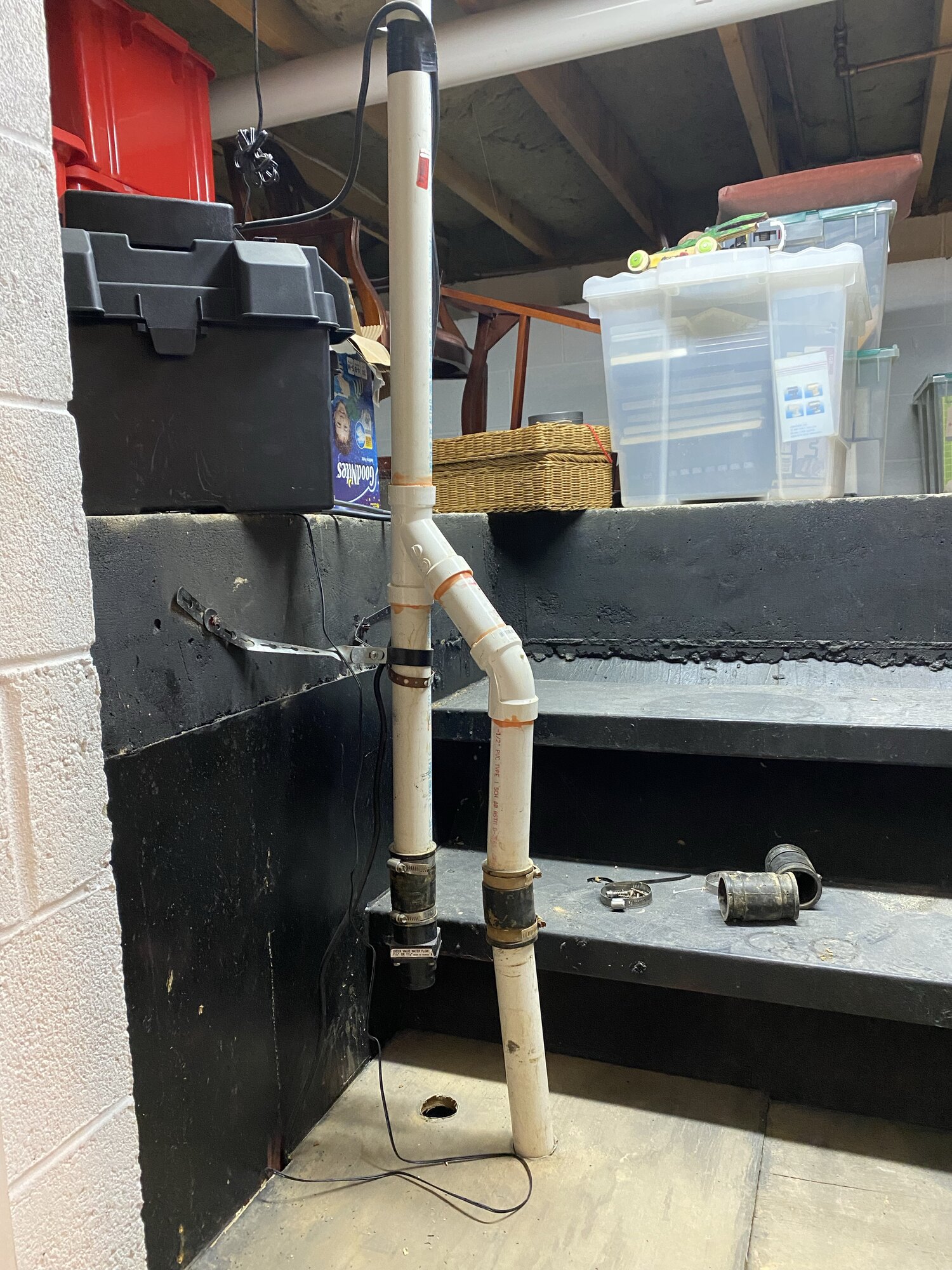
TBD — basement zone, pit size, discharge routing. The discharge stack photographed below (1½′′ PVC Sch 40 with check valve + Fernco couplings) is one of these three.
Pump · TBD · Backup · TBD
Component catalog
Brand / model / URL per component, captured progressively as labels surface during service. Each row is one bill-of-materials line.
Primary pump
Submersible sump pump — brand/model TBD per pit
The workhorse — runs on 120V household power, kicks on when the float sensor trips. Common 1/3 HP or 1/2 HP cast-iron submersibles (Zoeller M53, Liberty 257, Wayne CDU800, etc.). Capture model from the volute / data plate next time a pit is opened. Replacement cadence: 7–10 yr typical; cast-iron lasts longer than thermoplastic.
Product page TBD — Zoeller / Liberty / Wayne product URL once model confirmed
Battery-backup pump
DC-powered standby pump — brand/model TBD
Runs off the 12V battery when the primary fails or grid drops. Mounted higher in the pit so it only kicks in if water rises above the primary's float (or the primary fails). Common: Wayne ESP25, Zoeller 508 Aquanot, Liberty SJ10, Basement Watchdog Big Combo, PHCC Pro-Series. Discharges through its own check valve into a shared or separate riser. Test cadence: quarterly (pull primary's plug, pour water, confirm DC pump cycles).
Product page TBD
Backup battery
12V deep-cycle battery — brand/model TBD
Powers the DC backup pump during outages. Typical residential: 75–100 Ah deep-cycle marine / AGM. Lives in a vented battery box (the black case visible in the photo). Service: trickle-charged continuously by the backup-pump controller; full-replace every 3–5 yr (AGM) or 5–7 yr (lithium). Log purchase date on the battery's date sticker.
Product page TBD — capture from battery date sticker (e.g. Duracell AGM, Universal Power Group UB121000, NorthStar NSB-AGM31)
Level sensor
LevelGuard solid-state water sensor · UL E332036 · 120 VAC
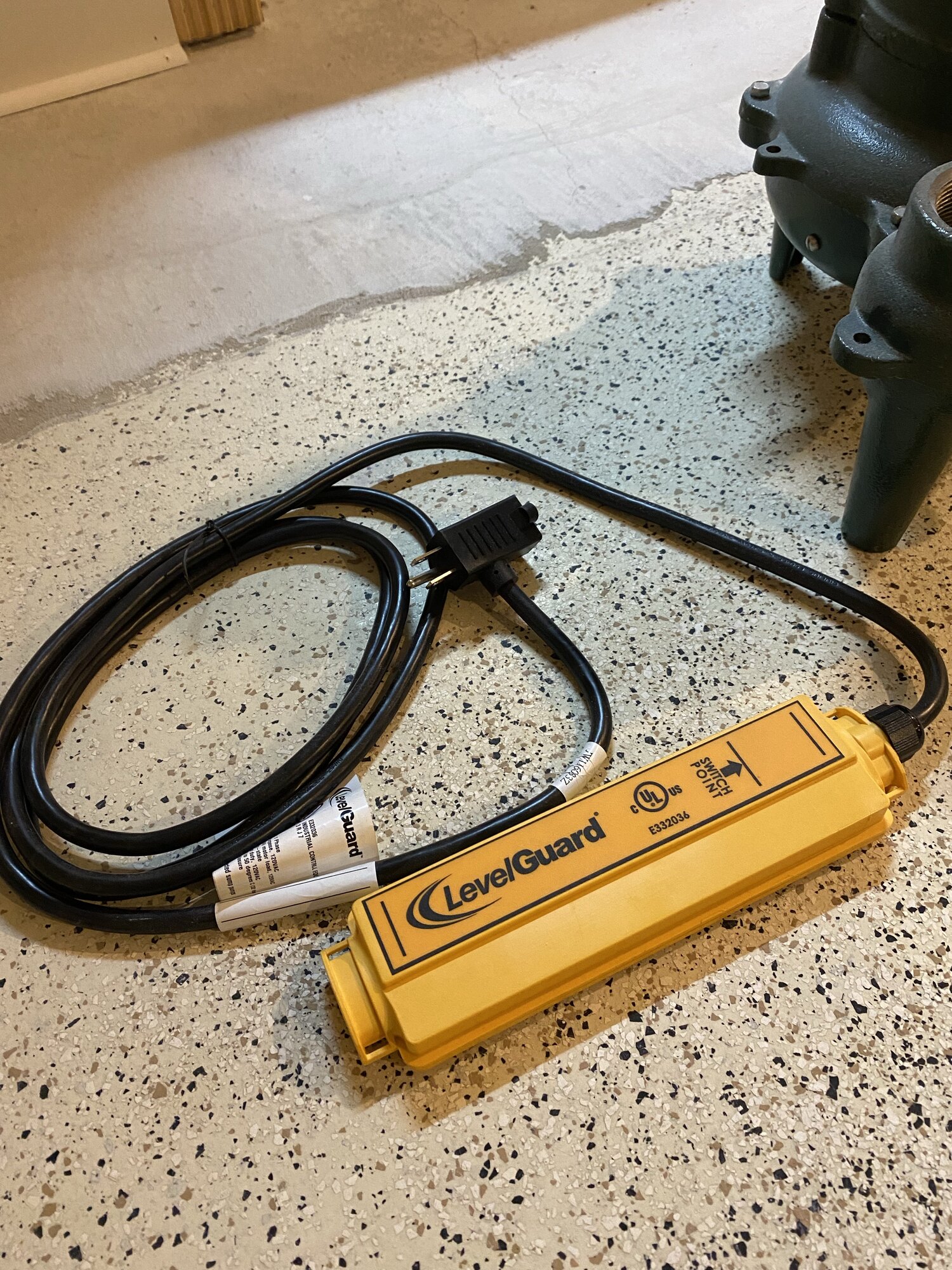
Tells the pump when to fire. Confirmed from the yellow housing photographed on file — LevelGuard (cUL listed under E332036, 120 VAC 1-phase). Solid-state — no moving float, no mechanical wear point. Two-prong cord + piggyback receptacle: the sensor cord plugs into the wall outlet, the pump's plug plugs into the back of the sensor — the sensor interrupts pump power when water hits the marked "SWITCH POINT" line on the body. Why solid-state matters: mechanical floats stick on debris build-up and silt; solid-state has no moving part to fail. Service: wipe the sensor strip with a cloth once a year; replace the whole unit every ~7–10 yr (no parts to service).
Brand site levelguard.com · UL listing UL file E332036
Check valve
Zoeller inline check valve · CE EN12050-4 · 1½′′
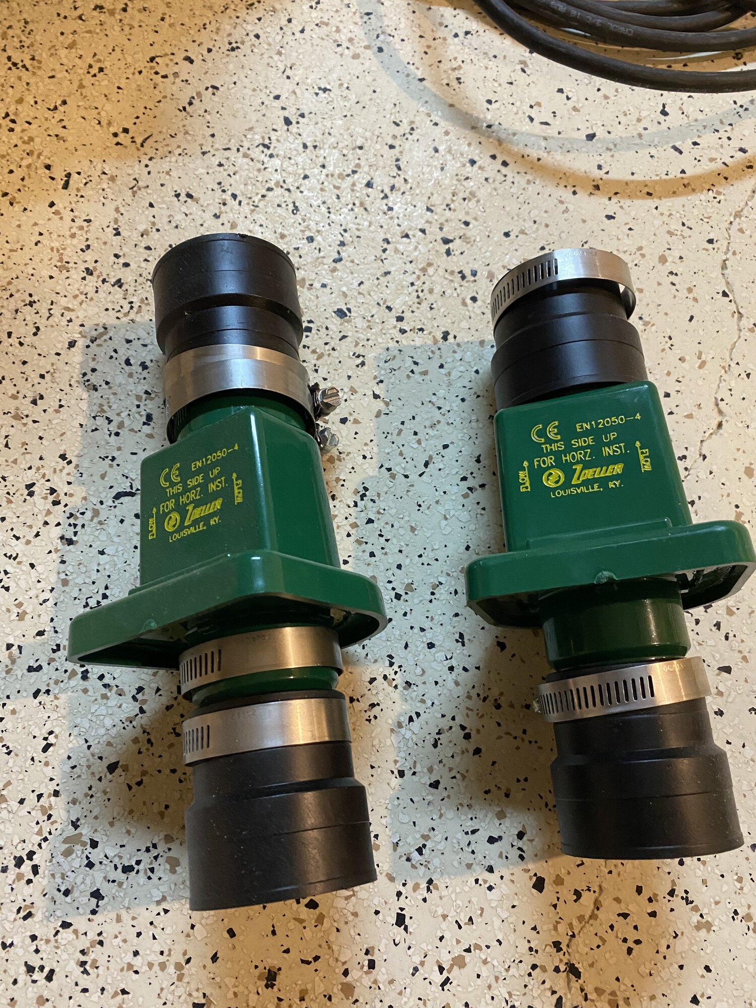
Confirmed from the green plastic housing photographed on file — Zoeller (Louisville, KY) · CE-marked EN12050-4 (European wastewater-pump compliance) · marked "THIS SIDE UP FOR HORZ. INST." with FLOW arrows. Inline barb-and-clamp body with rubber boots + stainless hose clamps each end (no solvent-cement joints, unscrews for pump-pull). Pattern is Zoeller's residential Quiet Check (30-0151 family). Two units on file — one per pump per riser (primary + battery-backup get independent check valves so a failed primary doesn't backflow into the backup loop). Installed ~6–18′′ above pit lid per NEC + pump-maker spec. Failure mode: spring weakens at 10+ yr → water "hammers" back into pit when pump stops, pump short-cycles. Diagnostic: listen for the thunk-of-hammer the moment the pump stops — that's the failure signal.
Product line Zoeller check valves · Manufacturer zoeller.com (Louisville KY, family-owned since 1939)
Discharge piping
1½′′ PVC Schedule 40 · ASTM D-1785
Confirmed from the photographed riser: 1½′′ PVC Schedule 40, ASTM-spec — the standard residential sump discharge size. Joined with primer + solvent cement at rigid fittings, transitioned to the pit-collar with rubber Fernco couplings (visible in photo) so the pump can be pulled without cutting pipe. Exits the rim joist, runs to grade, terminates at a splash-block or pop-up emitter ≥10′ from the foundation per code.
Spec sheet PVC Sch 40 dimensional spec (ASTM D-1785)
Photo strip
Service log
No entries yet. First entries should capture: (1) make/model/serial for each of the three pits' primary + backup pumps, (2) the backup battery's date sticker (purchase + install date), (3) the Level Guard model number from its sticker, (4) a quarterly-test result (pull primary's plug, pour water, confirm DC pump cycles, log seconds-to-cycle), (5) any tripped-but-no-water "ghost cycles" suggesting a stuck float. Date-stamped above-the-fact going forward.
Cross-references
- Well water — sibling water-management surface (water IN to the house)
- Septic — sibling water-management surface (waste water OUT of the house)
- Home insurance — sump failure → basement flood is a covered-loss-or-not question; document the dual-pump + battery-backup posture for the underwriter
- Contractors — sump-service contractor lives here once engaged; basement-waterproofing-shortlist already pre-exists for the heavier-scope intrusion-management work