Plotting power out to the shed
Planning the new electrical run from the house to the shed at New Hope — the proposed underground route (the red dashed line in the photos), the load and circuit spec, permits, and a running log of decisions. This is a working plan for review with a licensed electrician and the township, not a final design; nothing here is wired yet.
The idea — a dedicated run to the shed
Bring a dedicated power feed from the house out to the shed so the outbuilding can carry its own load — the planned ductless mini-split, lighting, and general outlets — instead of relying on the light/temporary feed it has now.
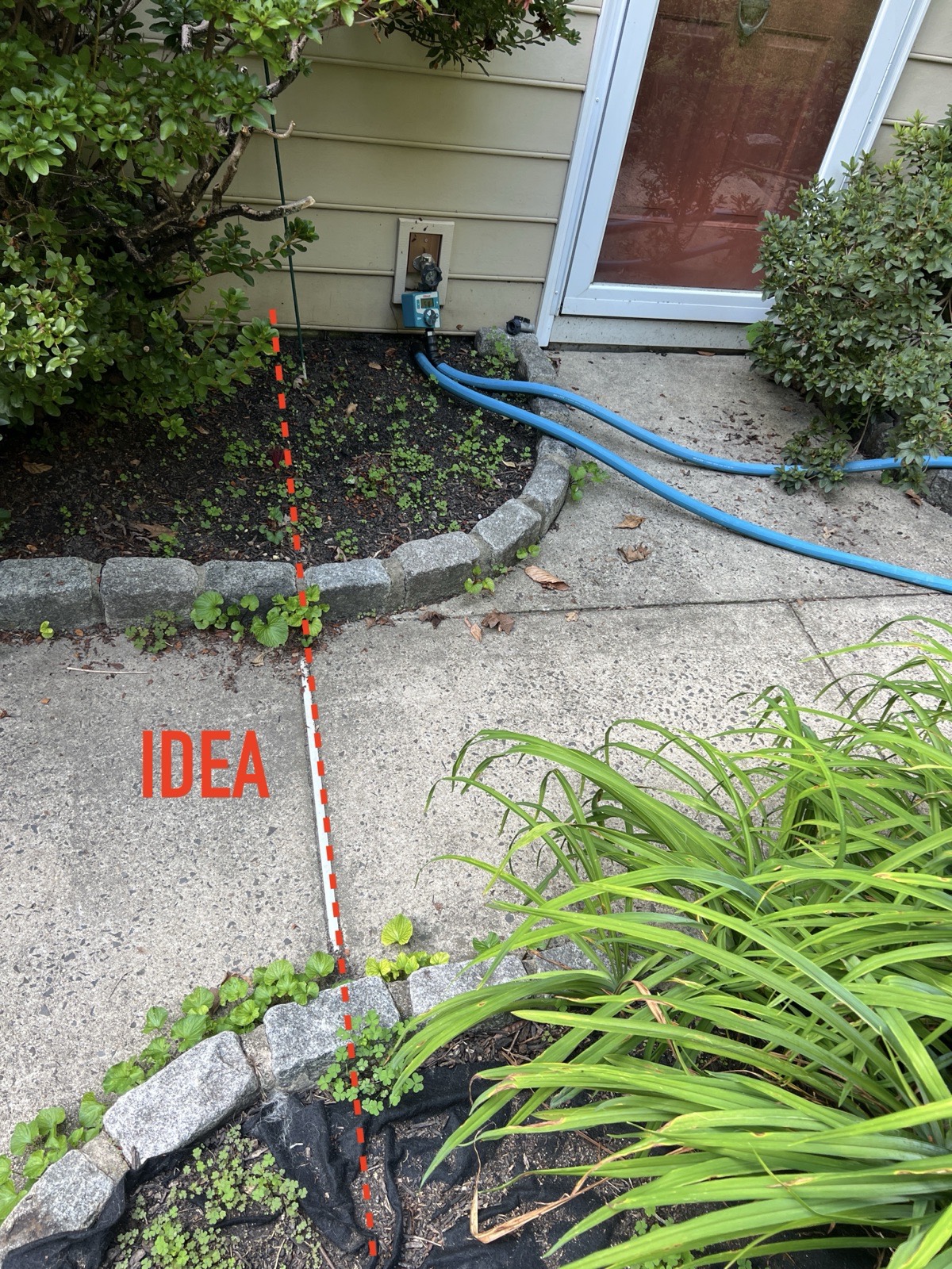
The proposed path taps the house near the back entrance and runs underground across the walkway and out through the lawn and beds to the shed. The red dashed line marked on the site photos below is that proposed route. Actual depth, conduit, and the exact tap point are for the electrician to confirm on site.
Same trade as the front-gate power-trench planning — if the timing lines up, the two runs could share one trench-and-conduit mobilisation.
Contractor plan — single-line diagram (Rev 0)
ASI Electrical Contractors issued a single-line diagram for the run on 9 Sep 2026 (Rev 0, initial issue). This moves the job from proposal to an issued plan — the conductor, conduit, panel, and grounding specs below are now as-drawn, not just working targets.
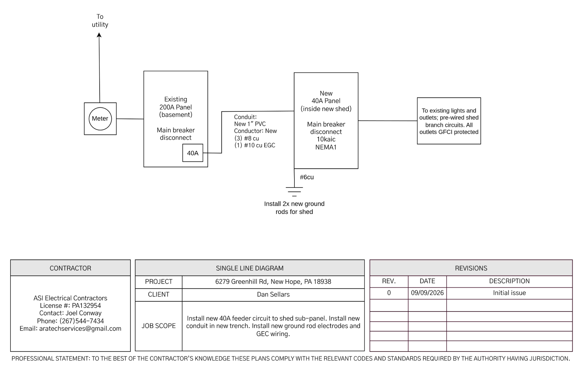
Site photos — the proposed route
Shots along the run — house end to shed end — plus the lengths paced off with a measuring wheel for the feeder sizing and voltage-drop check (see the wiring spec). The red dashed line is the route being considered, not a surveyed line; wheel readings are approximate. Tap any thumbnail to open the gallery, then use the arrows (or ← → / swipe) to scroll through.
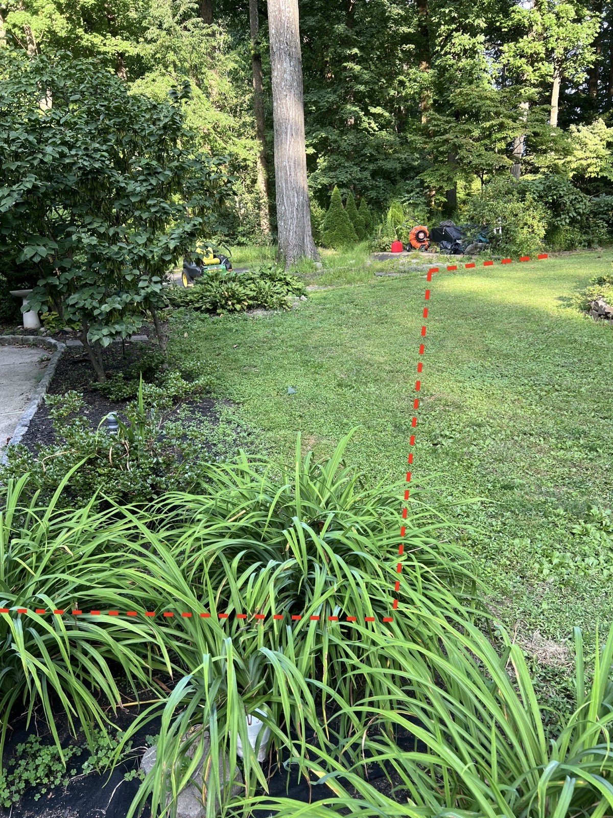 1 · house tap Feed leaves the house and crosses the front walk — likely a conduit sleeve under the slab.
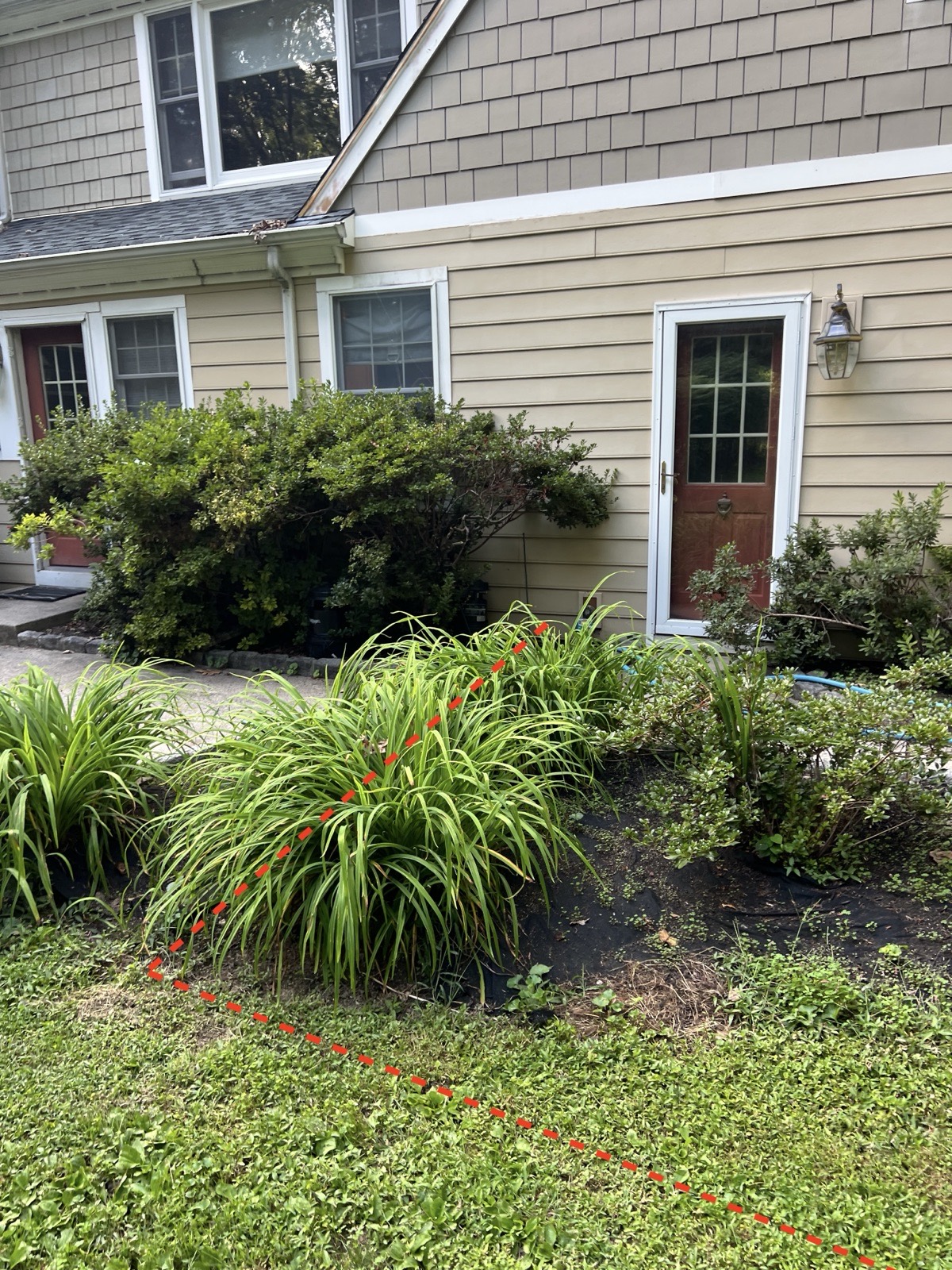 2 · along the house Through the planting bed toward the open lawn — softer digging.
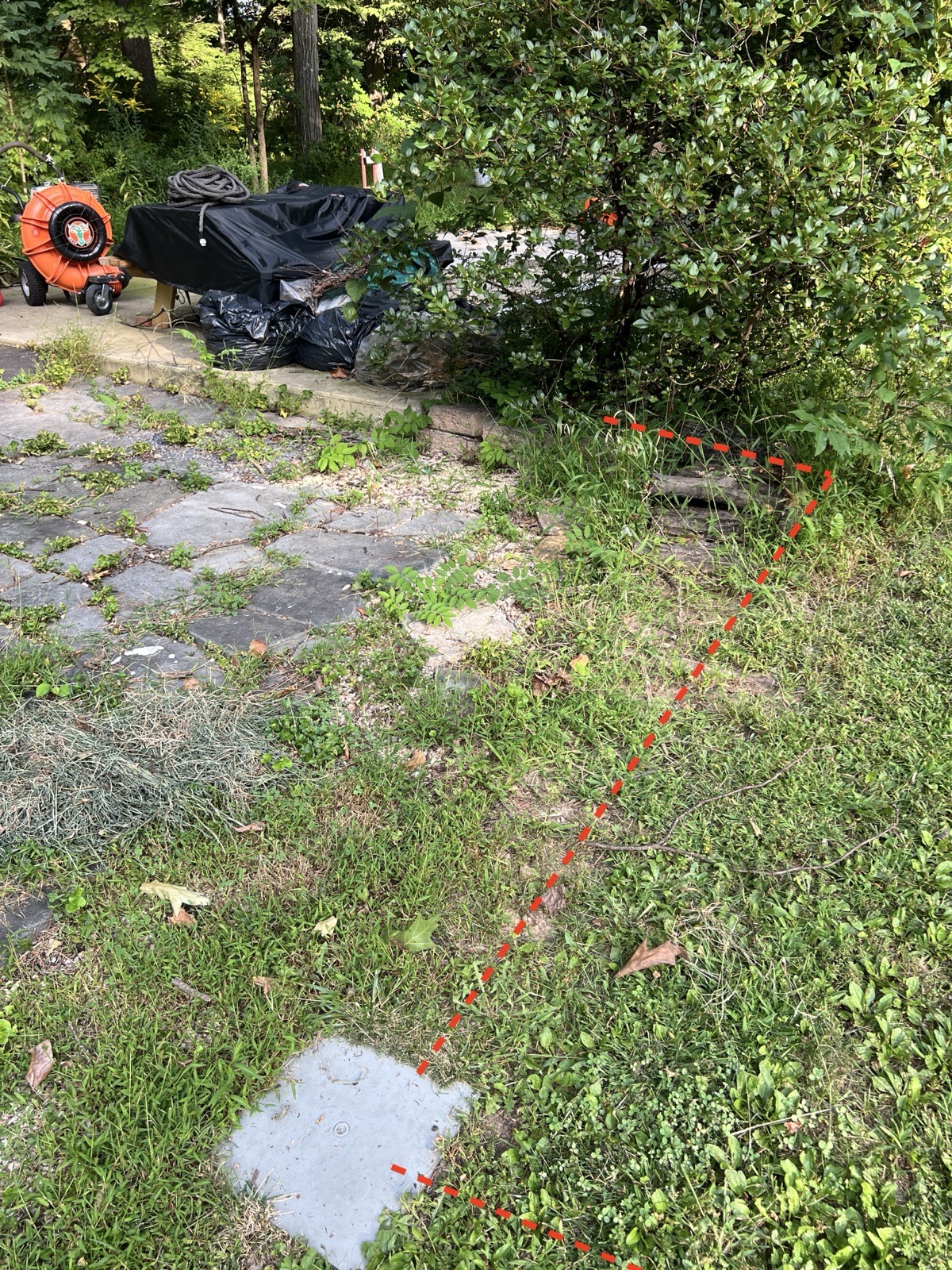 3 · across the lawn The long open stretch — the main trench length / run-distance leg.
 4 · shed end Run terminates and enters the shed; ground rod(s) land here.
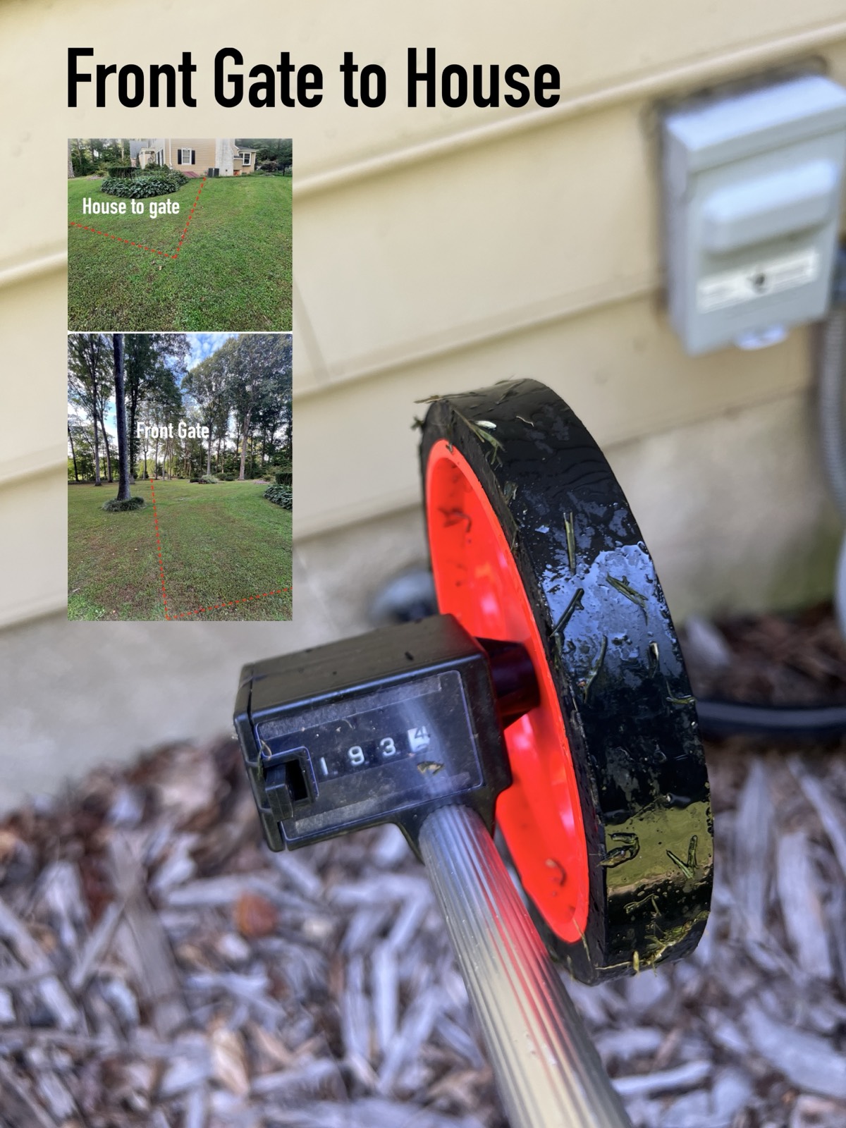 measure Front gate → house · wheel 1934
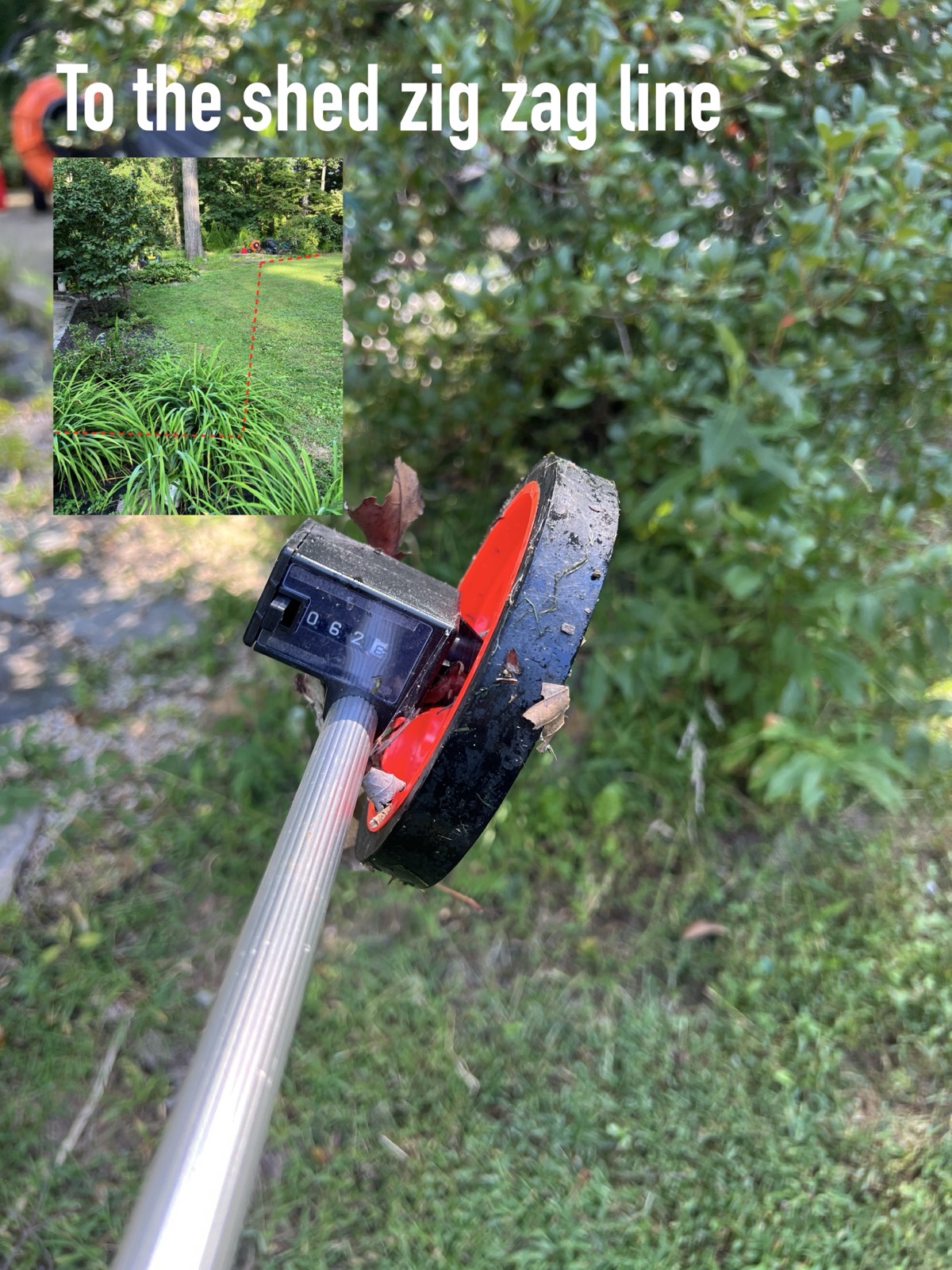 measure House → shed, zig-zag · wheel 0626
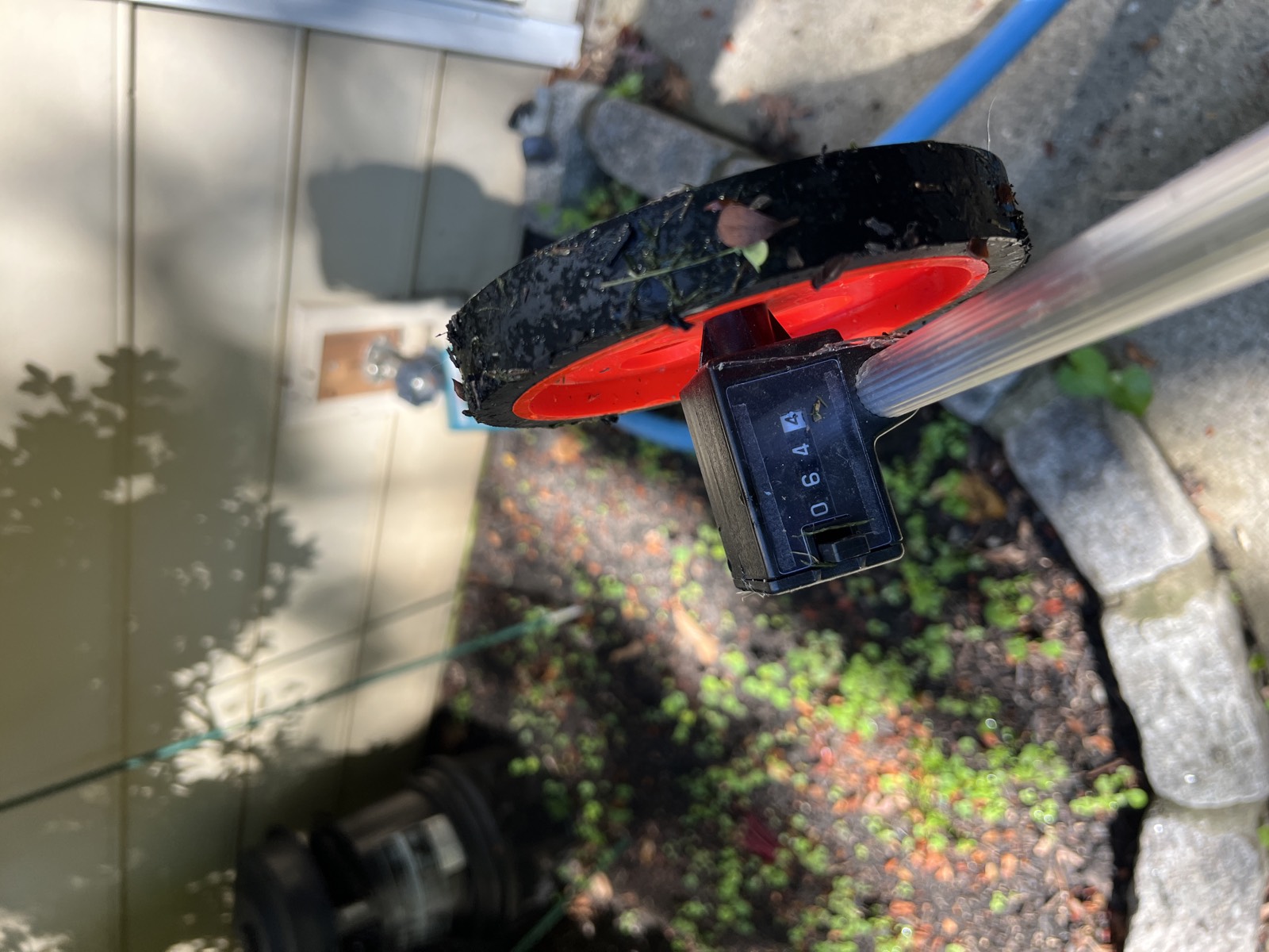 measure Counter — house end · close-up
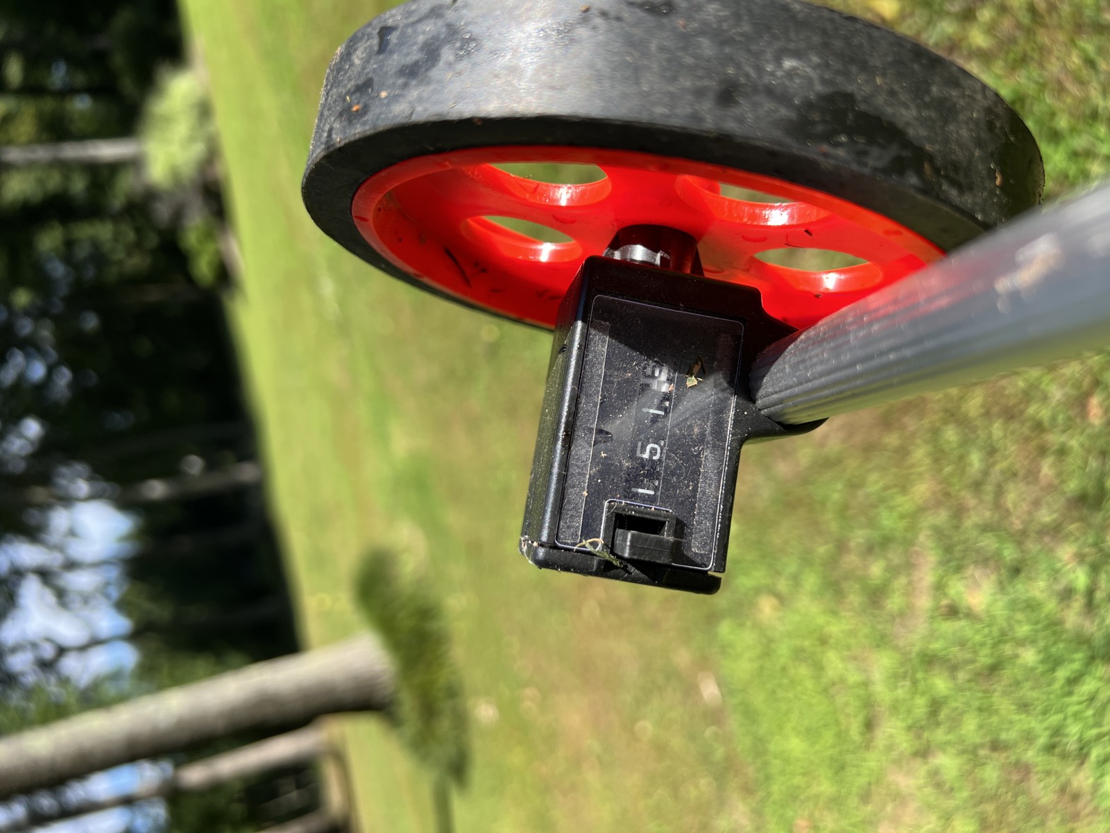 measure Counter — lawn waypoint · wheel 1515
Load & circuit
What that means in practice, to confirm with the electrician:
- 4-wire feed. A detached-building subpanel needs two hots, a neutral, and a separate equipment ground (four wires) under current code — neutral and ground kept separate at the shed, bonded only at the main house panel. The old 3-wire feed doesn't provide the separate ground, which is why it falls short.
- 40 A circuit. A 40 A, 240 V double-pole breaker at the house panel feeding a small subpanel at the shed — enough headroom for the mini-split plus lights and outlets. Conductor size follows from the 40 A rating and the run distance (voltage-drop over the lawn leg may push the gauge up); the electrician sizes the wire and conduit.
- Ground rod(s) at the shed for the subpanel, per code.
Wiring spec — conductors & conduit
A working spec for the 40 A, 4-wire feed, on the decision to pull individual conductors through conduit — the conduit is the physical protection, so this is not direct-burial (UF/USE) cable. Numbers to confirm with the electrician against Solebury Township / NEC.
Conductors — 40 A, 4-wire copper
- Two hots + neutral — #8 AWG copper.
THWN-2insulation (wet-rated — an underground conduit counts as a wet location). #8 Cu carries 50 A in the 75°C column, so it has margin on a 40 A breaker; only the two hots are current-carrying, so there's no conduit-fill derating penalty. - Equipment ground — #10 AWG copper. Per NEC 250.122, a 40 A circuit takes a #10 Cu ground. Kept separate from the neutral at the shed subpanel (bonded only at the main house panel).
- Four individual THWN-2 conductors pulled through the conduit — not a jacketed direct-burial cable. Matches the conduit-protective approach.
Conduit
- Type — PVC Schedule 40 for the buried run; step up to Schedule 80 (or rigid) anywhere it rises above grade or is exposed to damage — the risers at the house wall and shed, and the sleeve under the front walk.
- Size — 1″ recommended. 3/4″ is the code-minimum fill for four #8/#10 conductors, but 1″ fits #6 if voltage-drop pushes the gauge up (below), eases the long lawn pull, and leaves headroom. Pull a string.
- Depth — 18″ minimum cover for PVC conduit (NEC Table 300.5, residential 120/240 V). Concrete over the walk crossing counts toward that cover.
The run — segments & trenching
- House tap → walk crossing (photo 1). Leave the house near the back-door exterior circuit; cross the concrete front walk — likely bore or sleeve a conduit under the slab rather than cut it.
- Along the house bed (photo 2). Trench through the planting bed; easy digging, mind irrigation lines and the existing low-voltage/landscape wiring.
- Across the lawn (photo 3). The main trench length; THWN-2 conductors in PVC conduit at code depth (18″ cover). Measure this leg for the wire-sizing / voltage-drop math.
- Shed end (photo 4). Rise into the shed subpanel; set ground rod(s); make the building penetration weathertight.
Trench depth and the walk-crossing method remain the electrician's call against Solebury Township / NEC. Conduit type is settled — PVC (Sch 40 buried, Sch 80 on the risers) with individual THWN-2 conductors, per the wiring spec above.
Open questions — to verify
- Electrician + quote. Joel consulted on the circuit; get a scoped quote for the trench, feed, subpanel, and terminations. Open slot in contractors.
- Permit. An electrical permit is near-certain for a new detached-structure feed — confirm with Solebury Township (cross-ref land registry).
- Run length & voltage-drop. Measure the lawn leg; confirm the gauge is adequate over distance at 40 A.
- Panel size. 40 A now — but is it worth a larger subpanel/feed for future shed load while the trench is open?
- Walk crossing method. Sleeve/bore under the front walk vs saw-cut and patch.
- Combine with the gate-power trench? Same trade — one mobilisation if the timing works.
Working planning record for the New Hope shed. Photo route lines are illustrative, not surveyed. All circuit, conductor, depth, and permit details must be confirmed by a licensed electrician and the township before any work. Not an electrical design.